INTRODUCTION
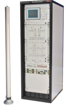
The DME Ground Station is a wide band navigation aid system which provides range information. It is compatible with all existing Airborne DME interrogators. The system is designed and manufactured to meet the requirements laid down in EUROCAE ED-57, RTCA DO-189 and ICAO Annex 10. In addition, all devices, material and tests are in accordance with above standards. The DME Ground Station is comprised of two sections: Transponder and Antenna. The DME Ground Station is fully solid state with state-of-the art technology using reliable FPGA based digital control loop for transmitter pulse shaping. In order to achieve high reliability, the redundancy is considered in system architecture. The modularity of the system is the important criterion that decreases diagnostic time. This system has 252 channels from 962 to 1213 MHz frequency range. This system operates in two modes, “X” and “Y” with 200 nautical miles coverage and capability to handle 200 aircrafts simultaneously.
FEATURES
● Built in Test
● Extremely high system reliability thanks to full redundancy and low repair time
● Simple maintenance and low life cycle costs
● Fully solid-state microprocessor controlled dual beacon equipment
● Modular Tuneless Solid State Power Amplifier
● Proven, time-tested antenna technology;
EUROCAE and ICAO flight certified.
SPECIFICATIONS
● High capacity system managing over 200 aircraft interrogators simultaneously
● With both full local and remote, for PC control and status indication
● Easy collocation with all types of VOR (DVOR) equipment.
● User-friendly interface that allows easy full control of DME Ground Station System.
● Supporting SNMP, UDP and TCP/IP
● Accuracy: ±50 m
TRANSMITTER
● Transmitter Frequency Range: 962 MHz to 1213 MHz
● X - Channel Pulse Pair Spacing: 12 µs
● Y - Channel Pulse Pair Spacing: 30 µs
● Pulse Shape and Spectrum: According to ICAO Annex 10
● Rise time: less than 3 µs (10% to 90%)
● Fall time: 2.5 µs (90% to 10%)
●
Pulse Spacing: According to ICAO Annex 10
● Peak Output Power: Max up to 1.5KW
ANTENNA
● Antenna Gain: 8.0 dBi main beam
● Gain, horizon: 6 dBi
● Circularity: ± 1 dB max on horizon
● Antenna Azimuth Coverage: Omni directional
● Antenna Polarization: Vertical
● VSWR: Less than 2 with respect to 50 ohm input.
● Power Rating: 10kW input power with 4% duty cycle
● _files/image733.png) Reply Delay: 50 µs nominal in X mode , 56 µs nominal in Y mode Programmable from 40 µs to 75 µs
Reply Delay: 50 µs nominal in X mode , 56 µs nominal in Y mode Programmable from 40 µs to 75 µs
● Reply Delay Stabilization: ±0.1 µs
● Inter Pulse Pair Spurious: at least 50 dB below weaker pulse peak power
● Channels: 252 (1X - 126X, 1Y - 126Y), 1 MHz Channel Spacing.
● Modulation type: AM
● Pulse width: 3.5 ± 0.5us Gaussian pulse according to ICAO Annex 10
● Duty Cycle: 5% max
● Frequency Deviation max: 10ppm
RECEIVER
● Transponder Reply Efficiency: > 70 %
● Receiver Frequency Range: 1025 MHz to 1150 MHz
● Receiver Dynamic Range: 80 dB
● Receiver Sensitivity: - 92dBm for 70% Reply Efficiency
● Receiver Frequency Stability: ±12 kHz
● Receiver Bandwidth: 350 ± 50kHz
● Receiver Recovery Time: 1µs
| Attachment | Size |
|---|---|
| chapter 6-11(127)_386.pdf | 389.63 KB |


